
.
Skin effect
Skin effect is the tendency of an alternating electric current (AC) to become distributed within a conductor such that the current density is largest near the surface of the conductor, and decreases with greater depths in the conductor. The electric current flows mainly at the "skin" of the conductor, between the outer surface and a level called the skin depth. The skin effect causes the effective resistance of the conductor to increase at higher frequencies where the skin depth is smaller, thus reducing the effective cross-section of the conductor. The skin effect is due to opposing eddy currents induced by the changing magnetic field resulting from the alternating current. At 60 Hz in copper, the skin depth is about 8.5 mm. At high frequencies the skin depth becomes much smaller. Increased AC resistance due to the skin effect can be mitigated by using specially woven litz wire. Because the interior of a large conductor carries so little of the current, tubular conductors such as pipe can be used to save weight and cost.
Cause
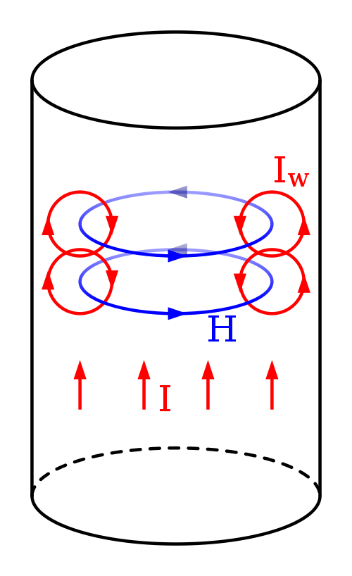
Skin depth is due to the circulating eddy currents (arising from a changing H field) cancelling the current flow in the center of a conductor and reinforcing it in the skin.
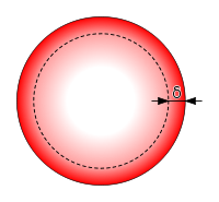
Distribution of current flow in a cylindrical conductor, shown in cross section. For alternating current, most (63%) of the electric current flows between the surface and the skin depth, δ, which depends on the frequency of the current and the electrical and magnetic properties of the conductor.
Conductors, typically in the form of wires, may be used to transmit electrical energy or signals using an alternating current flowing through that conductor. The charge carriers constituting that current, usually electrons, are driven by an electric field due to the source of electrical energy. An alternating current in a conductor produces an alternating magnetic field in and around the conductor. When the intensity of current in a conductor changes, the magnetic field also changes. The change in the magnetic field, in turn, creates an electric field which opposes the change in current intensity. This opposing electric field is called “counter-electromotive force” (back EMF). The back EMF is strongest at the center of the conductor, and forces the conducting electrons to the outside of the conductor, as shown in the diagram on the right. [1]
An alternating current may also be induced in a conductor due to an alternating magnetic field according to the law of induction. An electromagnetic wave impinging on a conductor will therefore generally produce such a current; this explains the reflection of electromagnetic waves from metals.
Regardless of the driving force, the current density is found to be greatest at the conductor's surface, with a reduced magnitude deeper in the conductor. That decline in current density is known as the skin effect and the skin depth is a measure of the depth at which the current density falls to 1/e of its value near the surface. Over 98% of the current will flow within a layer 4 times the skin depth from the surface. This behavior is distinct from that of direct current which usually will be distributed evenly over the cross-section of the wire.
The effect was first described in a paper by Horace Lamb in 1883 for the case of spherical conductors, and was generalised to conductors of any shape by Oliver Heaviside in 1885. The skin effect has practical consequences in the analysis and design of radio-frequency and microwave circuits, transmission lines (or waveguides), and antennas. It is also important at mains frequencies (50–60 Hz) in AC electrical power transmission and distribution systems. Although the term "skin effect" is most often associated with applications involving transmission of electric currents, the skin depth also describes the exponential decay of the electric and magnetic fields, as well as the density of induced currents, inside a bulk material when a plane wave impinges on it at normal incidence.
Formula
The AC current density J in a conductor decreases exponentially from its value at the surface JS according to the depth d from the surface, as follows:
\( J=J_\mathrm{S} \,e^{-{d/\delta }} \)
where δ is called the skin depth. The skin depth is thus defined as the depth below the surface of the conductor at which the current density has fallen to 1/e (about 0.37) of JS. The general formula for the skin depth is:[2][3]
\( \delta= \sqrt{{2\rho }\over{\omega\mu}} \; \; \sqrt{ \sqrt{1 + \left({\rho\omega\epsilon}\right)^2 } + \rho\omega\epsilon} \)
where
\( \rho \) = resistivity of the conductor
\( \omega \) = angular frequency of current = 2π × frequency
\( \mu_r \) = relative magnetic permeability of the conductor
\( \mu_0 \) = the permeability of free space
\( \mu = \mu_r \mu_0 \)
\( \epsilon_r \) = relative permittivity of the material
\(\epsilon_0 \) = the permittivity of free space
\(\epsilon = \epsilon_r \epsilon_0 \)
At frequencies much below \( 1/\rho \epsilon \) the quantity inside the large radical is close to unity and the formula is more usually given as:
\( \delta=\sqrt{{2\rho }\over{\omega\mu}}. \)
This formula is valid away from strong atomic or molecular resonances (where \( \epsilon \) would have a large imaginary part) and at frequencies which are much below both the material's plasma frequency (dependent on the density of free electrons in the material) and the reciprocal of the mean time between collisions involving the conduction electrons. In good conductors such as metals all of those conditions are ensured at least up to microwave frequencies, justifying this formula's validity. For example, in the case of copper, this would be true for frequencies much below 1018 Hz.
However in very poor conductors, at sufficiently high frequencies, the factor under the large radical increases. At frequencies much higher than \( 1/\rho \epsilon \) it can be shown that the skin depth, rather than continuing to decrease, approaches an asymptotic value:
\( \delta \approx {2 \rho} \sqrt{\epsilon \over \mu} \)
This departure from the usual formula only applies for materials of rather low conductivity and at frequencies where the vacuum wavelength is not much larger than the skin depth itself. For instance, bulk silicon (undoped) is a poor conductor and has a skin depth of about 40 meters at 100 kHz (λ = 3000 m). However as the frequency is increased well into the megahertz range, its skin depth never falls below the asymptotic value of 11 meters. The conclusion is that in poor solid conductors such as undoped silicon, the skin effect doesn't need to be taken into account in most practical situations: any current is equally distributed throughout the material's cross-section regardless of its frequency.
Resistance
The effective resistance due to a current confined near the surface of a large conductor (much thicker than δ) can be solved as if the current flowed uniformly through a layer of thickness δ based on the DC resistivity of that material. The effective cross-sectional area is approximately equal to δ times the conductor's circumference. Thus a long cylindrical conductor such as a wire, having a diameter D large compared to δ, has a resistance approximately that of a hollow tube with wall thickness δ carrying direct current. The AC resistance of a wire of length L and resistivity \rho is:
\( R\approx {{L \rho} \over {\pi (D-\delta) \delta}} \approx {{L \rho} \over {\pi D \delta}} \)
The final approximation above assumes D \gg \delta.
A convenient formula (attributed to F.E. Terman) for the diameter DW of a wire of circular cross-section whose resistance will increase by 10% at frequency f is:[4]
\( D_\mathrm{W} = {\frac{200~\mathrm{mm}}{\sqrt{f/\mathrm{Hz}}}} \)
The increase in AC resistance described above is accurate only for an isolated wire. For a wire close to other wires, e.g. in a cable or a coil, the ac resistance is also affected by proximity effect, which often causes a much more severe increase in ac resistance.
Material effect on skin depth
In a good conductor, skin depth is proportional to square root of the resistivity. This means that better conductors have a reduced skin depth. The overall resistance of the better conductor remains lower even with the reduced skin depth. However the better conductor will show a higher ratio between its AC and DC resistance, when compared with a conductor of higher resistivity. For example, at 60 Hz, a 2000 MCM (1000 square millimetre) copper conductor has 23% more resistance than it does at DC. The same size conductor in aluminum has only 10% more resistance with 60 Hz AC than it does with DC.[5]
Skin depth also varies as the inverse square root of the permeability of the conductor. In the case of iron, its conductivity is about 1/7 that of copper. However being ferromagnetic its permeability is about 10,000 times greater. This reduces the skin depth for iron to about 1/38 that of copper, about 220 micrometres at 60 Hz. Iron wire is thus useless for A.C. power lines (except to add mechanical strength by serving as a core to a non ferromagnetic conductor like aluminum). The skin effect also reduces the effective thickness of laminations in power transformers, increasing their losses.
Iron rods work well for direct-current (DC) welding but it is impossible to use them at frequencies much higher than 60 Hz. At a few kilohertz, the welding rod will glow red hot as current flows through the greatly increased A.C. resistance resulting from the skin effect, with relatively little power remaining for the arc itself. Only non-magnetic rods can be used for high-frequency welding.
At 1 megahertz the skin effect depth in wet soil is about 5.03 m, in seawater it's about 0.25 m.[6]
Mitigation
A type of cable called litz wire (from the German Litzendraht, braided wire) is used to mitigate the skin effect for frequencies of a few kilohertz to about one megahertz. It consists of a number of insulated wire strands woven together in a carefully designed pattern, so that the overall magnetic field acts equally on all the wires and causes the total current to be distributed equally among them. With the skin effect having little effect on each of the thin strands, the bundle does not suffer the same increase in AC resistance that a solid conductor of the same cross-sectional area would due to the skin effect.[7]
Litz wire is often used in the windings of high-frequency transformers to increase their efficiency by mitigating both skin effect and proximity effect. Large power transformers are wound with stranded conductors of similar construction to litz wire, but employing a larger cross-section corresponding to the larger skin depth at mains frequencies.[8] Conductive threads composed of carbon nanotubes[9] have been demonstrated as conductors for antennas from medium wave to microwave frequencies. Unlike standard antenna conductors, the nanotubes are much smaller than the skin depth, allowing full utilization of the thread's cross-section resulting in an extremely light antenna.
High-voltage, high-current overhead power lines often use aluminum cable with a steel reinforcing core; the higher resistance of the steel core is of no consequence since it is located far below the skin depth where essentially no AC current flows.
In applications where high currents (up to thousands of amperes) flow, solid conductors are usually replaced by tubes, completely eliminating the inner portion of the conductor where little current flows. This hardly affects the AC resistance, but considerably reduces the weight of the conductor. The high strength but low weight of tubes substantially increases span capability. Tubular conductors are typical in electric power switchyards where the distance between supporting insulators may be several meters. Long spans generally exhibit physical sag but this does not affect electrical performance. To avoid losses, the conductivity of the tube material must be high.
In high current situations where conductors (round or flat busbar) may be between 5 and 50 mm thick the skin effect also occurs at sharp bends where the metal is compressed inside the bend and stretched outside the bend. The shorter path at the inner surface results in a lower resistance, which causes most of the current to be concentrated close to the inner bend surface. This will cause an increase in temperature rise in that region compared with the straight (unbent) area of the same conductor. A similar skin effect occurs at the corners of rectangular conductors (viewed in cross-section), where the magnetic field is more concentrated at the corners than in the sides. This results in superior performance (i.e. higher current with lower temperature rise) from wide thin conductors - e.g. "ribbon" conductors, where the effects from corners is effectively eliminated.
It follows that a transformer with a round core will be more efficient than an equivalent-rated transformer having a square or rectangular core of the same material.
Solid or tubular conductors may be silver-plated to take advantage of silver's higher conductivity. This technique is particularly used at VHF to microwave frequencies where the small skin depth requires only a very thin layer of silver, making the improvement in conductivity very cost effective. Silver plating is similarly used on the surface of waveguides used for transmission of microwaves. This reduces attenuation of the propagating wave due to resistive losses affecting the accompanying eddy currents; the skin effect confines such eddy currents to a very thin surface layer of the waveguide structure. The skin effect itself isn't actually combatted in these cases, but the distribution of currents near the conductor's surface makes the use of precious metals (having a lower resistivity) practical. Although it has a lower conductivity than copper and silver, gold plating is also used, because unlike copper and silver, it does not corrode. A thin corroded layer of copper or silver would have a low conductivity, and so would cause large power losses as the majority of the current would still flow through this layer.
NOTE: The heat-dependent manufacturing process for wire results in oxidation of the surface in the finished product. Therefore, the conductivity of the skin is significantly less than the underlying unoxidised base metal. It is to be expected that unless the oxidised surface material is removed, some loss of performance from the theoretical model will occur.
Examples
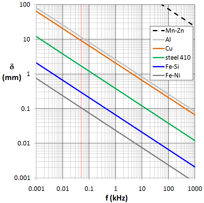
Skin depth vs. frequency for some materials, red vertical line denotes 50 Hz frequency:
Mn-Zn - magnetically soft ferrite
Al - metallic aluminum
Cu - metallic copper
steel 410 - magnetic stainless steel
Fe-Si - grain-oriented electrical steel
Fe-Ni - high-permeability permalloy (80%Ni-20%Fe)
We can derive a practical formula for skin depth as follows:
\( \delta=\sqrt{{2\rho }\over{(2 \pi f) (\mu_0 \mu_r)}} \approx 503\,\sqrt{\frac{\rho}{\mu_r f}} \)
where
\( \delta \) = the skin depth in meters
\( \mu_r \) = the relative permeability of the medium
\( \rho \) = the resistivity of the medium in Ω·m, also equal to the reciprocal of its conductivity: \rho = 1/ \(\sigma \) (for copper, ρ = 1.68×10⁻⁸ Ω·m)
f = the frequency of the current in Hz
Gold is a good conductor with a resistivity of 2.44×10⁻⁸ Ω·m and is essentially nonmagnetic: \mu_r = 1, so its skin depth at a frequency of 50 Hz is given by
\( \delta = 503 \,\sqrt{\frac{2.44 \cdot 10^{-8}}{1 \cdot 50}}= 11.1\,\mathrm{mm} \)
Lead, in contrast, is a relatively poor conductor (among metals) with a resistivity of 2.2×10⁻⁷ Ω·m, about 9 times that of gold. Its skin depth at 50 Hz is likewise found to be about 33 mm, or \( \sqrt{9} = 3 \) times that of gold.
Highly magnetic materials have a reduced skin depth owing to their large permeability \mu_r as was pointed out above for the case of iron, despite its poorer conductivity. A practical consequence is seen by users of induction cookers, where some types of stainless steel cookware are unusable because they are not ferromagnetic.[10]
At very high frequencies the skin depth for good conductors becomes tiny. For instance, the skin depths of some common metals at a frequency of 10 GHz (microwave region) are less than a micrometer:
Conductor Skin depth (μm)
Aluminum 0.80
Copper 0.65
Gold 0.79
Silver 0.64
Thus at microwave frequencies, most of the current flows in an extremely thin region near the surface. Ohmic losses of waveguides at microwave frequencies are therefore only dependent on the surface coating of the material. A layer of silver 3 μm thick evaporated on a piece of glass is thus an excellent conductor at such frequencies.
In copper, the skin depth can be seen to fall according to the square root of frequency:
| Conductor | Skin depth (μm) |
|---|---|
| Aluminum | 0.80 |
| Copper | 0.65 |
| Gold | 0.79 |
| Silver | 0.64 |
In Engineering Electromagnetics, Hayt points out that in a power station a busbar for alternating current at 60 Hz with a radius larger than one-third of an inch (8 mm) is a waste of copper, and in practice bus bars for heavy AC current are rarely more than half an inch (12 mm) thick except for mechanical reasons.
Skin effect reduction of the self inductance of a conductor
Refer to the diagram below showing the inner and outer conductors of a coaxial cable. Since the skin effect causes a current at high frequencies to flow mainly at the surface of a conductor, it can be seen that this will reduce the magnetic field inside the wire, that is, beneath the depth at which the bulk of the current flows. It can be shown that this will have a minor effect on the self-inductance of the wire itself; see Skilling[11] or Hayt[12] for a mathematical treatment of this phenomenon.
Note that the inductance considered in this context refers to a bare conductor, not the inductance of a coil used as a circuit element. The inductance of a coil is dominated by the mutual inductance between the turns of the coil which increases its inductance according to the square of the number of turns. However when only a single wire is involved, then in addition to the "external inductance" involving magnetic fields outside of the wire (due to the total current in the wire) as seen in the white region of the figure below, there is also a much smaller component of "internal inductance" due to the magnetic field inside the wire itself, the green region in figure B. In a single wire the internal inductance becomes of little significance when the wire is much much longer than its diameter. The presence of a second conductor in the case of a transmission line requires a different treatment as is discussed below.
Due to the skin effect, at high frequencies the internal inductance of a wire vanishes, as can be seen in the case of a telephone twisted pair, below. In normal cases the effect of internal inductance is ignored in the design of coils or calculating the properties of microstrips.
Inductance per length in a coaxial cable
Let the dimensions a, b, and c be the inner conductor radius, the shield (outer conductor) inside radius and the shield outer radius respectively, as seen in the crossection of figure A below.
Four stages of skin effect in a coax showing the effect on inductance. Diagrams show a cross-section of the coaxial cable. Color code: black=overall insulating sheath, tan=conductor, white=dielectric, green=current into the diagram, blue=current coming out of the diagram, dashed black lines with arrowheads=magnetic flux (B). The width of the dashed black lines is intended to show relative strength of the magnetic field integrated over the circumference at that radius. The four stages, A, B, C, and D are non-energized, low frequency, middle frequency and high frequency respectively. There are three regions that may contain induced magnetic fields: the center conductor, the dielectric and the outer conductor. In stage B, current covers the conductors uniformly and there is a significant magnetic field in all three regions. As the frequency is increased and the skin effect takes hold (C and D) the magnetic field in the dielectric region is unchanged as it is proportional to the total current flowing in the center conductor. In C, however, there is a reduced magnetic field in the deeper sections of the inner conductor and the outer sections of the shield (outer conductor). Thus there is less energy stored in the magnetic field given the same total current, corresponding to a reduced inductance. At an even higher frequency, D, the skin depth is tiny: all current is confined to the surface of the conductors. The only magnetic field is in the regions between the conductors; only the "external inductance" remains.
For a given current, the total energy stored in the magnetic fields must be the same as the calculated electrical energy attributed to that current flowing through the inductance of the coax; that energy is proportional to the cable's measured inductance.
The magnetic field inside a coaxial cable can be divided into three regions, each of which will therefore contribute to the electrical inductance seen by a length of cable.[13]
The inductance \(L_\text{cen} \, \) is associated with the magnetic field in the region with radius \( r < a \, , \) the region inside the center conductor.
The inductance \(L_\text{ext} \, \) is associated with the magnetic field in the region \( a < r < b \, , \) the region between the two conductors (containing a dielectric, possibly air).
The inductance L_\text{shd} \, is associated with the magnetic field in the region \( b < r < c \, , \) the region inside the shield conductor.
The net electrical inductance is due to all three contributions:
\( L_\text{total} = L_\text{cen} + L_\text{shd} + L_\text{ext}\, \)
L_\text{ext} \, is not changed by the skin effect and is given by the frequently cited formula for inductance L per length D of a coaxial cable:
\( L/D = \frac{\mu_0}{2 \pi} \ln \left( \frac {b}{a} \right) \, \)
At low frequencies, all three inductances are fully present so that \( L_\text{DC} = L_\text{cen} + L_\text{shd} + L_\text{ext}\, . \)
At high frequencies, only the dielectric region has magnetic flux, so that \( L_\infty = L_\text{ext}\, . \)
Most discussions of coaxial transmission lines assume they will be used for radio frequencies, so equations are supplied corresponding only to the latter case.
As the skin effect increases, the currents are concentrated near the outside of the inner conductor (r=a) and the inside of the shield (r=b). Since there is essentially no current deeper in the inner conductor, there is no magnetic field beneath the surface of the inner conductor. Since the current in the inner conductor is balanced by the opposite current flowing on the inside of the outer conductor, there is no remaining magnetic field in the outer conductor itself where \( b < r < c \, \) . Only \( L_\text{ext} \) contributes to the electrical inductance at these higher frequencies.
Although the geometry is different, a twisted pair used in telephone lines is similarly affected: at higher frequencies the inductance decreases by more than 20% as can be seen in the following table.
Characteristics of telephone cable as a function of frequency
Representative parameter data for 24 gauge PIC telephone cable at 21 °C (70 °F).
| Frequency (Hz) | R (Ω/km) | L (mH/km) | G (μS/km) | C (nF/km) |
|---|---|---|---|---|
| 1 | 172.24 | 0.6129 | 0.000 | 51.57 |
| 1k | 172.28 | 0.6125 | 0.072 | 51.57 |
| 10k | 172.70 | 0.6099 | 0.531 | 51.57 |
| 100k | 191.63 | 0.5807 | 3.327 | 51.57 |
| 1M | 463.59 | 0.5062 | 29.111 | 51.57 |
| 2M | 643.14 | 0.4862 | 53.205 | 51.57 |
| 5M | 999.41 | 0.4675 | 118.074 | 51.57 |
More extensive tables and tables for other gauges, temperatures and types are available in Reeve.[14] Chen[15] gives the same data in a parameterized form that he states is usable up to 50 MHz.
Chen[15] gives an equation of this form for telephone twisted pair:
\( L(f) = \frac {l_0 + l_{\infty}(\frac{f}{f_m})^b }{1 + (\frac{f}{f_m})^b} \, \)
See also
Proximity effect (electromagnetism)
Penetration depth
Eddy currents
Litz wire
Transformer
Induction Cooking
Induction heating
Magnetic Reynolds number
Notes
"These emf's are greater at the center than at the circumference, so the potential difference tends to establish currents that oppose the current at the center and assist it at the circumference" Fink, Donald G.; Beaty, H. Wayne (2000). Standard Handbook for Electrical Engineers (14th ed.). McGraw-Hill. p. 2-50. ISBN 0-07-022005-0.
Vander Vorst, Rosen & Kotsuka (2006)
The formula as shown is algebraically equivalent to the formula found on page 130 Jordan (1968, p. 130)
Terman 1943, p. ??
Fink, Donald G.; Beatty, H. Wayne, eds. (1978), Standard Handbook for Electrical Engineers (11th ed.), McGraw Hill, p. Table 18-21
Popovic & Popovic 1999, p. 385
Xi Nan & Sullivan 2005
Central Electricity Generating Board (1982). Modern Power Station Practice. Pergamon Press.
"Spinning Carbon Nanotubes Spawns New Wireless Applications". Sciencedaily.com. 2009-03-09. Retrieved 2011-11-08.
If the permeability is low, the skin depth is so large that the resistance encountered by eddy currents is too low to provide enough heat
Skilling (1951, pp. 157–159)
Hayt (1981, pp. 434–439)
Hayt (1981, p. 434)
Reeve (1995, p. 558)
Chen (2004, p. 26)
References
Chen, Walter Y. (2004), Home Networking Basics, Prentice Hall, ISBN 0-13-016511-5
Hayt, William (1981), Engineering Electromagnetics (4th ed.), McGraw-Hill, ISBN 0-07-027395-2
Hayt, William Hart. Engineering Electromagnetics Seventh Edition. New York: McGraw Hill, 2006. ISBN 0-07-310463-9.
Nahin, Paul J. Oliver Heaviside: Sage in Solitude. New York: IEEE Press, 1988. ISBN 0-87942-238-6.
Ramo, S., J. R. Whinnery, and T. Van Duzer. Fields and Waves in Communication Electronics. New York: John Wiley & Sons, Inc., 1965.
Ramo, Whinnery, Van Duzer (1994). Fields and Waves in Communications Electronics. John Wiley and Sons.
Reeve, Whitman D. (1995), Subscriber Loop Signaling and Transmission Handbook, IEEE Press, ISBN 0-7803-0440-3
Skilling, Hugh H. (1951), Electric Transmission Lines, McGraw-Hill
Terman, F. E. (1943), Radio Engineers' Handbook, New York: McGraw-Hill
Xi Nan; Sullivan, C. R. (2005), "An equivalent complex permeability model for litz-wire windings" (PDF), Industry Applications Conference 3: 2229–2235, doi:10.1109/IAS.2005.1518758, ISBN 0-7803-9208-6, ISSN 0197-2618
Jordan, Edward Conrad (1968), Electromagnetic Waves and Radiating Systems, Prentice Hall, ISBN 978-0-13-249995-8
Vander Vorst, Andre; Rosen, Arye; Kotsuka, Youji (2006), RF/Microwave Interaction with Biological Tissues, John Wiley and Sons, Inc., ISBN 978-0-471-73277-8
Popovic, Zoya; Popovic, Branko (1999), Chapter 20,The Skin Effect, Introductory Electromagnetics, Prentice-Hall, ISBN 978-0201326789
Retrieved from "http://en.wikipedia.org/"
All text is available under the terms of the GNU Free Documentation License
