| - Art Gallery - |
In physics, a magnetic field is a field that permeates space and which exerts a magnetic force on moving electric charges and magnetic dipoles. Magnetic fields surround electric currents, magnetic dipoles, and changing electric fields. When placed in a magnetic field, magnetic dipoles align their axes to be parallel with the magnetic field, as can be seen when iron filings are in the presence of a magnet (see picture at right). Magnetic fields also have their own energy and momentum, with an energy density proportional to the square of the field intensity. The magnetic field is typically measured in either teslas (SI units) or gauss (cgs units). There are some notable specific incarnations of the magnetic field. For the physics of magnetic materials, see magnetism and magnet, and more specifically ferromagnetism, paramagnetism, and diamagnetism. For constant magnetic fields, such as are generated by stationary dipoles and steady currents, see magnetostatics. For magnetic fields created by changing electric fields, see electromagnetism. The electric field and the magnetic field are closely interlinked due to Einstein's theory of special relativity (see relativistic electromagnetism). Together, they make up the electromagnetic field. Definition
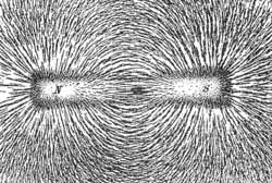
Magnetic field lines shown by iron filings. The high permeability of individual iron filings causes the magnetic field to be larger at the ends of the filings. This causes individual filings to attract each other, forming elongated clusters that trace out the appearance of lines. It would not be expected that these "lines" be precisely accurate field lines for this magnet; rather, the magnetization of the iron itself would be expected to alter the field somewhat. In classical physics,the magnetic field The field (There are, in addition, several other different but physically equivalent ways to define the magnetic field, for example via the Lorentz force law (see below), or as the solution to Maxwell's equations.) It follows from any of these definitions that the magnetic field vector (being a vector product) is a pseudovector (also called an axial vector). In a bar magnet, for example, the direction of the magnetic field is as follows: In the interior of the magnet, it points roughly towards the magnet's north pole; and outside the magnet, it points roughly towards the magnet's south pole.[1] B and H There are two quantities that physicists may refer to as the magnetic field, notated The difference between the (1) Magnetic induction current causes a magnetic current density
was essentially a rotational analogy to the linear electric current relationship, (2) Electric convection current
where ρ is electric charge density. The electric current equation can be viewed as a convective current of electric charge that involves linear motion. By analogy, the magnetic equation is an inductive current involving spin. There is no linear motion in the inductive current along the direction of the The extension of the above considerations confirms that where In SI units, The fields
where Force due to a magnetic field Main article: Lorentz force Force on a charged particle
where F is the force (in newtons) Force on current-carrying wire A straight, stationary wire carrying an electric current, when placed in an external magnetic field, feels a force. This force is the result of the Lorentz force (see above) acting on each electron (or any other charge carrier) moving in the wire. The formula for the total force is as follows:
where F = Force, measured in newtons Alternatively, some authors write
where the vector direction is now associated with the current variable, instead of the length variable. The two forms are equivalent. If the wire is not straight but curved, the force on it can be computed by applying this formula to each infinitesimal segment of wire, then adding up all these forces via integration. The Lorentz force on a macroscopic current is often referred to as the Laplace force.
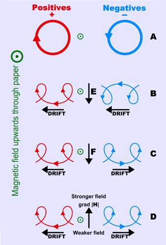
Charged particle drifts in a homogenous magnetic field. (A) No disturbing force (B) With an electric field, E (C) With an independent force, F (eg. gravity) (D) In an inhomgeneous magnetic field, grad H
Demonstration of Fleming's left hand rule Direction of force The direction of force is determined by the above equations, in particular using the right-hand rule to evaluate the cross product. Equivalently, one can use Fleming's left hand rule for motion, current and polarity to determine the direction of any one of those from the other two, as seen in the example. It can also be remembered in the following way. The digits from the thumb to second finger indicate 'Force', 'B-field', and 'I(Current)' respectively, or F-B-I in short. Another similar trick is the right hand grip rule. Magnetic field of a steady current Main article: Biot-Savart law The magnetic field generated by a steady current (a continual flow of charges, for example through a wire, which is constant in time and in which charge is neither building up nor depleting at any point), is described by the Biot-Savart law: (in SI units), where I is the current, μ0 is the magnetic constant, r is the distance from the wire element to the point at which the field is being computed. This is a consequence of Ampere's law, one of the four Maxwell's equations. Alternatively, it can be thought of as a true, empirical law in its own right, which contributes to the derivation of Maxwell's equations. From a practical point of view, though, the law is true and useful regardless of its philosophical origin. Properties Magnetic field lines Like any vector field, the magnetic field can be depicted with field lines -- a set of lines through space whose direction at any point is the direction of the local magnetic field vector, and whose density is proportional to the magnitude of the local magnetic field vector. Note that the choice of which field lines to draw in such a depiction is arbitrary, apart from the requirement that they be spaced out so that their density approximates the magnitude of the local field. The level of detail at which the magnetic field is depicted can be increased by increasing the number of lines. Although any vector field can be depicted with field lines, this visualization is particularly helpful for the magnetic field (in three-dimensional space), as it makes certain aspects of it more transparent. For example, "Gauss's law for magnetism" states that the magnetic field is solenoidal (has zero divergence). This is equivalent to the simple statement that, in any field-line depiction of a magnetic field, the field lines cannot have starting or ending points; they must form a closed loop, or else extend to infinity on both ends. Various physical phenomena have the effect of displaying field lines. For example, iron filings placed in a magnetic field will line up in such a way as to visually show magnetic field lines (see figure at top); although a close inspection will reveal that the "lines" are not quite continuous. Another place where magnetic field lines are visually displayed is in the polar auroras, in which visible streaks of light line up with the local direction of Earth's magnetic field (due to plasma particle dipole interactions). Note that when a magnetic field is depicted with field lines, it is not meant to imply that the field is only nonzero along the drawn-in field lines. The field is typically smooth and continuous everywhere, and can be estimated at any point (whether on a field line or not) by looking at the direction and density of the field lines nearby. The use of iron filings to display a field presents something of an exception to this picture: the magnetic field is in fact much larger along the "lines" of iron, due to the large permeability of iron relative to air. The direction of the magnetic field corresponds to the direction that a magnetic dipole (such as a small magnet) will orient itself in that magnetic field (see definition above). Therefore, a cluster of small particles of ferromagnetic material, such as iron filings, placed in the magnetic field will line up in such a way as to visually show the magnetic field lines (see figure at top). Another place where magnetic field lines are visually displayed is the polar auroras, in which visible streaks of light line up with the local direction of Earth's magnetic field. Pole labelling confusions See also North Magnetic Pole and South Magnetic Pole. The end of a compass needle that points north was historically called the "north" magnetic pole of the needle. Since dipoles are vectors and align "head to tail" with each other to minimize their magnetic potential energy, the magnetic pole located near the geographic North Pole is actually the "south" pole. The "north" and "south" poles of a magnet or a magnetic dipole are labelled similarly to north and south poles of a compass needle. Near the north pole of a bar or a cylinder magnet, the magnetic field vector is directed out of the magnet; near the south pole, into the magnet. This magnetic field continues inside the magnet (so there are no actual "poles" anywhere inside or outside of a magnet where the field stops or starts). Breaking a magnet in half does not separate the poles but produces two magnets with two poles each. Earth's magnetic field is probably produced by electric currents in its liquid core. Rotating magnetic fields Main article: Alternator The rotating magnetic field is a key principle in the operation of alternating-current motors. A permanent magnet in such a field will rotate so as to maintain its alignment with the external field. This effect was conceptualized by Nikola Tesla, and later utilised in his, and others, early AC (alternating-current) electric motors. A rotating magnetic field can be constructed using two orthogonal coils with 90 degrees phase difference in their AC currents. However, in practice such a system would be supplied through a three-wire arrangement with unequal currents. This inequality would cause serious problems in standardization of the conductor size and so, in order to overcome it, three-phase systems are used where the three currents are equal in magnitude and have 120 degrees phase difference. Three similar coils having mutual geometrical angles of 120 degrees will create the rotating magnetic field in this case. The ability of the three-phase system to create a rotating field, utilized in electric motors, is one of the main reasons why three-phase systems dominate the world's electrical power supply systems. Because magnets degrade with time, synchronous motors and induction motors use short-circuited rotors (instead of a magnet) following the rotating magnetic field of a multicoiled stator. The short-circuited turns of the rotor develop eddy currents in the rotating field of the stator, and these currents in turn move the rotor by the Lorentz force. In 1882, Nikola Tesla identified the concept of the rotating magnetic field. In 1885, Galileo Ferraris independently researched the concept. In 1888, Tesla gained U.S. Patent 381,968 for his work. Also in 1888, Ferraris published his research in a paper to the Royal Academy of Sciences in Turin. Hall effect Main article: Hall effect Because the Lorentz force is charge-sign-dependent (see above), it results in charge separation when a conductor with current is placed in a transverse magnetic field, with a buildup of opposite charges on two opposite sides of conductor in the direction normal to the magnetic field, and the potential difference between these sides can be measured. The Hall effect is often used to measure the magnitude of a magnetic field as well as to find the sign of the dominant charge carriers in semiconductors (negative electrons or positive holes). Special relativity and electromagnetism Main article: Relativistic electromagnetism According to special relativity, electric and magnetic forces are part of a single physical phenomenon, electromagnetism; an electric force perceived by one observer will be perceived by another observer in a different frame of reference as a mixture of electric and magnetic forces. A magnetic force can be considered as simply the relativistic part of an electric force when the latter is seen by a moving observer. More specifically, rather than treating the electric and magnetic fields as separate fields, special relativity shows that they naturally mix together into a rank-2 tensor, called the electromagnetic tensor. This is analogous to the way that special relativity "mixes" space and time into spacetime, and mass, momentum and energy into four-momentum. Magnetic field shape descriptions
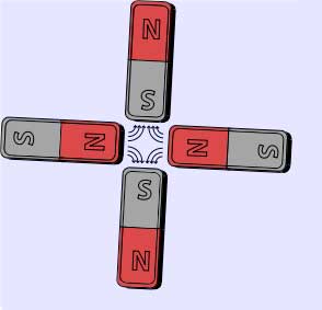
Schematic quadrupole magnet("four-pole") magnetic field. There are four steel pole tips, two opposing magnetic north poles and two opposing magnetic south poles * An azimuthal magnetic field is one that runs east-west. * A meridional magnetic field is one that runs north-south. In the solar dynamo model of the Sun, differential rotation of the solar plasma causes the meridional magnetic field to stretch into an azimuthal magnetic field, a process called the omega-effect. The reverse process is called the alpha-effect.[4] * A dipole magnetic field is one seen around a bar magnet or around a particle with nonzero spin. * A quadrupole magnetic field is one seen, for example, between the poles of four bar magnets. The field strength grows linearly with the radial distance from its longitudinal axis. * A solenoidal magnetic field is similar to a dipole magnetic field, except that a solid bar magnet is replaced by a hollow electromagnetic coil magnet. * A toroidal magnetic field occurs in a doughnut-shaped coil, the electric current spiraling around the tube-like surface, and is found, for example, in a tokamak. * A poloidal magnetic field is generated by a current flowing in a ring, and is found, for example, in a tokamak. See also General * Electric field — effect produced by an electric charge that exerts a force on charged objects in its vicinity. Mathematics * Ampère's law — magnetic equivalent of Gauss's law. Applications * Helmholtz coil — a device for producing a region of nearly uniform magnetic field. References Web * Nave, R., Magnetic Field Strength H, <http://hyperphysics.phy-astr.gsu.edu/hbase/magnetic/magfield.html>. Retrieved on 4 June 2007 * Oppelt, Arnulf (2006-11-02), magnetic field strength, <http://searchsmb.techtarget.com/sDefinition/0,290660,sid44_gci763586,00.html>. Retrieved on 4 June 2007 * magnetic field strength converter, <http://www.unitconversion.org/unit_converter/magnetic-field-strength.html>. Retrieved on 4 June 2007 Books * Durney, Carl H. and Johnson, Curtis C. (1969). Introduction to modern electromagnetics. McGraw-Hill. ISBN 0-07-018388-0. * Tipler, Paul (2004). Physics for Scientists and Engineers: Electricity, Magnetism, Light, and Elementary Modern Physics (5th ed.). W. H. Freeman. ISBN 0-7167-0810-8. * Furlani, Edward P. (2001). Permanent Magnet and Electromechanical Devices: Materials, Analysis and Applications. Academic Press Series in Electromagnetism. ISBN 0-12-269951-3. Notes 1. ^ http://en.allexperts.com/q/Physics-1358/magnetic-field-lines-depicted.htm 2. ^ Magnetic Field Strength is also sometimes called Magnetic Field Intensity. For more information reference the sources Durney and Johnson, and also Rao. 3. ^ The standard graduate textbook by Jackson follows this usage. Edward Purcell, in Electricity and Magnetism, McGraw-Hill, 1963, writes, Even some modern writers who treat B as the primary field feel obliged to call it the magnetic induction because the name magnetic field was historically preempted by H. This seems clumsy and pedantic. If you go into the laboratory and ask a physicist what causes the pion trajectories in his bubble chamber to curve, he'll probably answer "magnetic field," not "magnetic induction." You will seldom hear a geophysicist refer to the earth's magnetic induction, or an astrophysicist talk about the magnetic induction of the galaxy. We propose to keep on calling B the magnetic field. As for H, although other names have been invented for it, we shall call it "the field H" or even "the magnetic field H". 4. ^ The Solar Dynamo, retrieved Sep 15, 2007. Links Information * Crowell, B., "Electromagnetism". Field density * Jiles, David (1994). Introduction to Electronic Properties of Materials (1st ed.). Springer. ISBN 0-412-49580-5. Rotating magnetic fields * "Rotating magnetic fields". Integrated Publishing. Diagrams * McCulloch, Malcolm,"A2: Electrical Power and Machines", Rotating magnetic field. eng.ox.ac.uk. Journal Articles * Yaakov Kraftmakher, "Two experiments with rotating magnetic field". 2001 Eur. J. Phys. 22 477-482. Retrieved from "http://en.wikipedia.org/"  |
|