
.
Diffraction grating
In optics, a diffraction grating is an optical component with a surface covered by a regular pattern of parallel lines, typically separated by a distance comparable to the wavelength of light. Light rays that pass through such a surface are bent as a result of diffraction, related to the wave properties of light. This diffraction angle depends on the wavelength of the light. In its simplest form, a diffraction grating could be a photographic slide with a fine pattern of black lines. However, for practical applications, most gratings have grooves or rulings on their surface rather than dark lines. Such gratings can be either transparent or reflective. Because of their ability of splitting light into different wavelengths (dispersion), gratings are commonly used in monochromators and spectrometers.
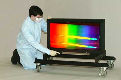
A very large reflecting diffraction grating.
For a given grating, light with a larger wavelength generally has a larger diffraction angle. More precisely, a single wavelength can simultaneously have multiple discrete diffraction angles, called diffraction orders.
The principles of difraction gratings were discovered by James Gregory (astronomer and mathematician), about a year after Newton's Prism experiments, initially with artefacts such as bird feathers.The first man-made diffraction grating was made around 1785 by Philadelphia inventor David Rittenhouse, who strung hairs between two finely threaded screws. This was similar to notable German physicist Joseph von Fraunhofer's wire diffraction grating in 1821.
Theory of operation
Main article: diffraction
Gratings are usually designated by their groove density, the number of grooves per unit length, usually expressed in grooves per millimeter (g/mm), also equal to the inverse of the groove period. The groove period must be on the order of the wavelength of interest; the spectral range covered by a grating is dependent on groove spacing and is the same for ruled and holographic gratings with the same grating constant. The maximum wavelength that a grating can diffract is equal to twice the grating period, in which case the incident and diffracted light will be at ninety degrees to the grating normal. To obtain frequency dispersion over a wider frequency one must use a prism. In the optical regime, in which the use of gratings is most common, this corresponds to wavelengths between 100 nm and 10 µm. In that case, the groove density can vary from a few tens of grooves per millimeter, as in echelle gratings, to a few thousands of grooves per millimeter.
A fundamental property of gratings is that the angle of deviation of all but one of the diffracted beams depends on the wavelength of the incident light. Therefore, a grating separates an incident polychromatic beam into its constituent wavelength components, i.e., it is dispersive. Each wavelength of input beam spectrum is sent into a different direction, producing a rainbow of colors under white light illumination. This is visually similar to the operation of a prism, although the mechanism is very different.
When a beam is incident on a grating with an angle θi (measured from the normal of the grating), it is diffracted into several beams. The beam that corresponds to direct transmission (or specular reflection in the case of a reflection grating) is called the zero order, and is denoted m = 0. The other orders correspond to diffraction angles which are represented by non-zero integers m. For a groove period d and an incident wavelengh λ, the grating equation gives the value of the diffracted angle θm(λ) in the order m:
![]()
Note that m can be positive or negative, resulting in diffracted orders on both sides of the zero order beam. Note also that there exist various conventions for choosing the sign of the angles, possibly resulting in different signs in the grating equation.
The diffracted beams corresponding to consecutive orders may overlap, depending on the spectral content of the incident beam and the grating density. The higher the spectral order, the greater the overlap into the next order.
The grating equation shows that the angles of the diffracted orders only depend on the grooves' period, and not on their shape. By controlling the cross-sectional profile of the grooves, it is possible to concentrate most of the diffracted energy in a particular order for a given wavelength. A triangular profile is commonly used. This technique is called blazing. The incident angle and wavelength for which the diffraction is most efficient are often called blazing angle and blazing wavelength. The efficiency of a grating may also depend on the polarization of the incident light.
When groove spacing is less than half the wavelength of light, the only present order is the m = 0 order. Gratings with such small periodicity are called subwavelength gratings and exhibit special optical properties. Made on an isotropic material the subwavelength gratings give rise to form birefringence, in which the material behaves as if it were birefringent.
Diffraction gratings can be produced by modulating one of the following material properties:
* transparency (transmission amplitude gratings)
* reflectance (reflection amplitude gratings)
* refractive index (phase gratings)
* direction of optical axis (optical axis gratings) (phase gratings in birefringent materials and subwavelength gratings)
Fabrication
Originally, high-resolution gratings were ruled using high-quality ruling engines whose construction was a large undertaking. Henry Joseph Grayson designed a machine to make diffraction gratings, succeeding with one of 120,000 lines to the inch (approx. 47 000 per cm) in 1899. Later, photolithographic techniques allowed gratings to be created from a holographic interference pattern. Holographic gratings have sinusoidal grooves and may not be as efficient as ruled gratings, but are often preferred in monochromators because they lead to much less stray light. A copying technique allows high quality replicas to be made from master gratings, thereby lowering fabrication costs.
Another method for manufacturing diffraction gratings uses a photosensitive gel sandwiched between two substrates. A holographic interference pattern exposes the gel which is later developed. These gratings, called volume phase holography diffraction gratings (or VPH diffraction gratings) have no physical grooves, but instead a periodic modulation of the refractive index within the gel. This removes much of the surface scattering effects typically seen in other types of gratings. These gratings also tend to have higher efficiencies, and allow for the inclusion of complicated patterns into a single grating. In older versions of such gratings, environmental susceptibility was a trade-off, as the gel had to be contained at low temperature and humidity. Typically, the photosensitive substances are sealed between two substrates which make them resistant to humidity, thermal and mechanical stresses. VPH diffraction gratings are not destroyed by accidental touches and are more scratch resistant than typical relief gratings.
Semiconductor technology today is also utilized to etch holographically patterned gratings into robust materials as fused silica. In this way, low stray-light holography is combined with the high efficiency of deep, etched transmission gratings, and can be incorporated into high volume, low cost semiconductor manufacturing technology.
Examples
Diffraction gratings are often used in monochromators, spectrometers, wavelength division multiplexing devices, optical pulse compressing devices, and many other optical instruments. In fact, Dispersion Bridge technology for planar lightwave circuits, which is based on diffraction gratings, will likely displace thin-film filter technology and other bulk optics approaches to processing optical signals in both fiber to the home and wavelength division multiplexing devices.
Ordinary pressed CD and DVD media are every-day examples of diffraction gratings and can be used to demonstrate the effect by reflecting sunlight off them onto a white wall. This is a side effect of their manufacture, as one surface of a CD has many small pits in the plastic, arranged within concentric rings; that surface has a thin layer of metal applied to make the pits more visible. The structure of a DVD is optically similar, although it may have more than one pitted surface, and all pitted surfaces are inside the disc.
The image sensor of a digital camera has a fine pattern which can produce a diffraction artifact on the image.
Diffraction gratings are also present in nature. For example, the iridescent colors of peacock feathers, mother-of-pearl, butterfly wings, and some other insects are caused by very fine regular structures that diffract light, splitting it into its component colors.
See also
* Henry Augustus Rowland
Links
* Diffraction Grating Equations
* How to build a diffraction spectrometer
* Photograph of a lightbulb seen through a diffraction grating.
References
* Adapted from a public domain entry in Federal Standard 1037C.
* National Optical Astronomy Observatories entry regarding volume phase holography gratings.
* Palmer, Christopher, Diffraction Grating Handbook, 6th edition, Newport Corporation (2005). [1]
* Greenslade, Thomas B., "Wire Diffraction Gratings," The Physics Teacher, February 2004. Volume 42 Issue 2, pp. 76-77. [2]
* Abrahams, Peter Early Instruments of Astronomical Spectroscopy. [3]
Retrieved from "http://en.wikipedia.org/"
All text is available under the terms of the GNU Free Documentation License
